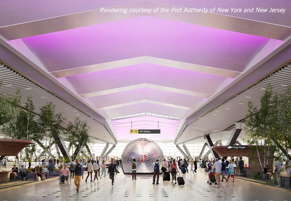
JFK New Terminal One
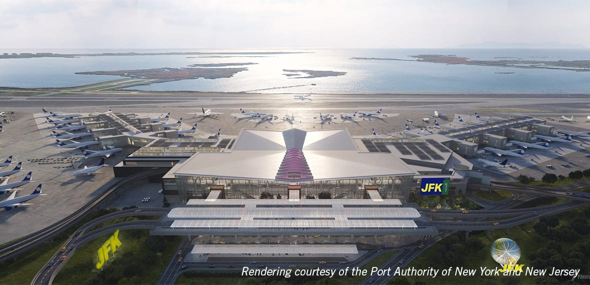
Arora Engineers (Arora) provided engineering, project controls, and construction phase services to the design/build team led by AECOM Tishman for the P3 delivery of the new Terminal One at John F. Kennedy International Airport (JFK), privately financed by a consortium of labor, operating and financial partners, including Ferrovial, Carlyle, JLC Infrastructure, and Ullico.
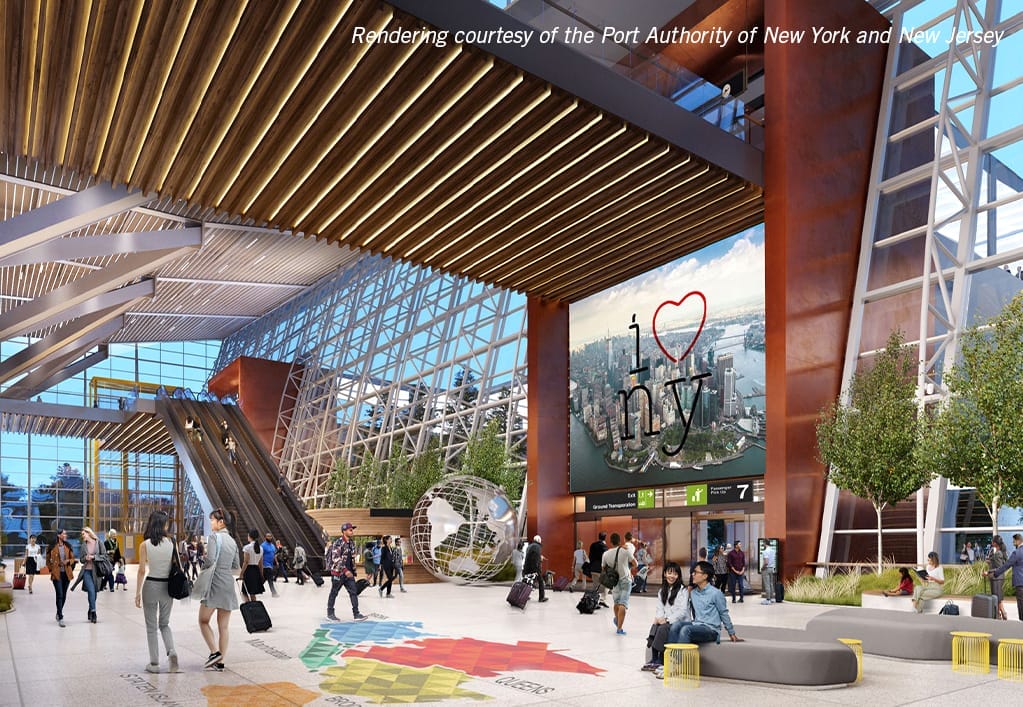
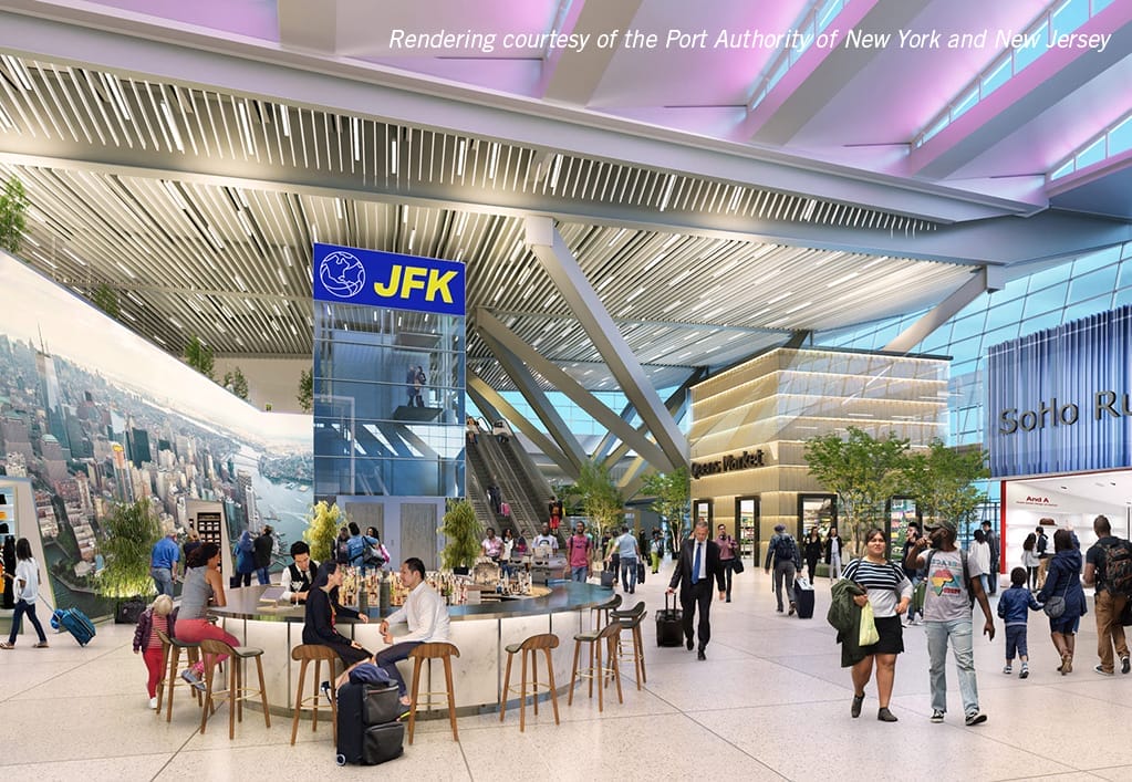
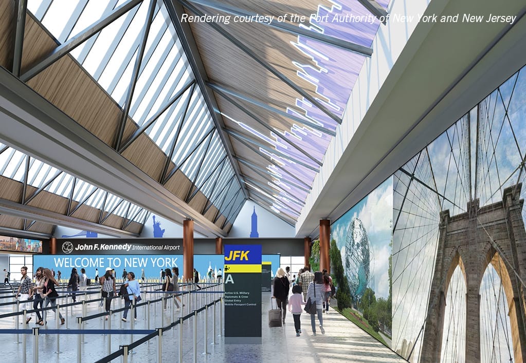
The new Terminal One aims to redefine international travel at JFK with 23 international gates, 22 of which will be designed to accommodate larger, wide-body aircraft (FAA Airplane Design Group V or VI), and a total terminal area of 2.4M SF. The new terminal will contain approximately 24 security screening lanes, state-of-the-art baggage handling system, over 300,000SF of retail, dining, and other concessions, 116,000SF of airline lounges, and 55,000SF of interior green space, children’s play areas, and cultural exhibits. The new terminal includes the main headhouse/processor, east pier, and the airside hardstand elements.
In alignment with the Authority’s commitment to reach net-zero greenhouse gas emissions by 2050, the Terminal will feature sustainable solutions such as on-site renewable energy generation, electric ground support equipment and optimized lighting and building controls.
Arora served as engineer of record under AECOM for the electrical, communications, domestic water, natural gas, chilled water, thermal distribution, and sanitary site utilities, and led airfield electrical engineering, highmast Lighting, eGSE charging, and PBB systems coordination services. In addition, Arora provided fire protection engineering services as a subconsultant to JB&B.
Site Utilities Scope: Initially, the team ensured all existing utility systems in and adjacent to the new terminal construction site were identified and those portions which had to be removed or abandoned in place were taken out of service in a methodical manner as construction advanced. Services to existing Terminals 1 and 2 and other facilities were sufficiently maintained until the services were no longer needed, and temporary connections / bypasses were provided.
- Sanitary – The team began by verifying existing system routes and potential termination and reconnection locations, then met with JFK maintenance staff to review system operation. Advanced work included the design and construction of an interim sanitary sewer force main (SSFM), with lift station, opposite existing Terminal 1 which will collect and convey Terminal 1 and Terminal 2 discharge flow. The interim SSFM was sized to accommodate existing T-1 sanitary discharge. The force main was routed along the south and east sides of the proposed headhouse/processor to an existing sanitary manhole and gravity system at the northeast lower level of the project.
- Thermal Distribution System (TDS) Chilled Water (CHW) and Medium Temperature Hot Water (MTHW) – The team first confirmed existing routes, connection locations and work restrictions, then developed designs for CHW and MTHW due to seasonal restrictions. Arora led the design which included construction of 30” black steel dual pipe (supply and return) CHW and 16” black steel triple pipe (supply, return, alternate) MTHW system. Interim TDS by-pass connections between existing CHW and MTHW lines and Terminal 1 were maintained during Phase A construction of the headhouse/processor.
Portions of the permanent CHW and MTHW pipes were installed in the Utility Corridor in the front of the headhouse/ processor in order to facilitate this connection and will remain in place under the final design configuration. At the completion of Phase A, the MTHW and CHW service will be commissioned to the new building and allow terminal 1 to be decommissioned and demolished. Arora designed the pipe sizes and connections for interim and final pipe configurations. The MTHW was designed to include 2N redundancy with 2 supply and 2 return with a spare.
- Low Pressure Domestic Water – The team verified existing system routes, valves and hydrant locations, then met with JFK mechanical maintenance staff on operation of the existing system and discussed specific problem areas within the new terminal 1 construction site. Temporary service was maintained to Terminal 1 and fire hydrants within the Lease Limits during Phase A construction. Arora designed the permanent domestic water service consisted of a 24” Ductile Iron Pipe (DIP) watermain in the utility corridor, 12” DIP fire loop around the east pier, headhouse/processor, and west pier as well as fire hydrants on the landside and airside.
- Natural Gas – In coordination with National Grid, Arora confirmed existing routes and discussed their requirements and procedures for changes to the existing gas system. Arora designed new natural gas site utilities in coordination with National Grid, and coordination was maintained with National Grid on an ongoing basis.
- Electric – Arora was responsible for the power distribution and lighting design. The team began by verifying existing routes and potential termination and connection points, then met with JFK electrical maintenance staff to confirm information was accurate and discussed procedures/protocols pertaining to work on the electrical system. Electrical service to Terminal 1 was maintained by re-routing existing feeders to Terminal 1. Permanent power to the New Terminal 1 will be provided by a new substation.
- Communication – The team reviewed the system within the construction area and coordinated with the various interested parties (FAA, TSA, Customs, PANYNJ, Telcom firms, etc.) to gather information on the various systems, procedures, and protocols. Existing communications to Terminal 1 and other Port Authority facilities originates within Communications Rooms housed on the first (grade) level of the “Green Garage”.
This garage is scheduled for demolition, and demolition plans are currently being prepared. Arora designed the temporary communications which were rerouted using the Air Train guide box as a pathway until the permanent duct bank was constructed and fiber was installed. In addition to maintaining and protecting critical existing communications infrastructure during demolition of the Green Garage, Arora was responsible for temporary and permanent communications facilities which were coordinated to clear the footprint of the Headhouse/Processor phased construction.
- Meeter Greeter – Arora was responsible for the required supporting power, lighting, and telecommunications designs for the Meeter Greeter. Arora provided design services to power the gate guard operations, provide area lighting and obstruction lights, as well as FAA required solar lights.
- EV Bus Charging Stations- Arora provided design services for the supporting power, lighting, and telecommunications required for the EV Bus Charging Stations Design. Designs included 600-1200A @ 480V 3PH, and a new panelboard/switchgear to feed the units.
- Area 4 Trailer Complex – Arora designed the required supporting sanitary, electrical, domestic water, and telecommunications for the landside/airside utilities associated with the Area 4 Trailer complex. The design included 10-15 toilets and 8 sinks which would provide for up to 100 people, and a single service point for sanitary and water so that the trailers could be interconnected.
The team began by verifying existing system routes and potential termination and reconnection locations for sanitary, then met with JFK maintenance staff to review system operation, with a goal of tapping into Sanitary across the street to supply low pressure domestic water. Arora was also responsible for the power distribution and lighting design. The team began by verifying existing routes and potential termination and connection points, then met with JFK electrical maintenance staff to confirm information was accurate and discussed procedures/protocols pertaining to work on the electrical system.
In parallel with construction of the communication duct bank and vaults, Arora completed validation of existing active fiber optic and copper cable plant in the demolition area. The process identified and categorized all active communication cables, documented their origin/splice points and their end user device (EUD) locations and functions. Once origin locations outside of the demolition area were determined, Arora designed the reroute of the cable temporarily using the Air Train guide box as a pathway. Arora designed permanent communication lines from the existing communication vaults outside the construction area to the new Terminal 1 and other airport facilities.
Airfield Electrical, Highmast Lighting, eGSE charging, and PBB Systems Coordination Scope: Arora’s scope of work included the supporting sanitary, electrical, telecommunications, lighting and eGSE design required for the airside utilities.
The eGSE battery charger system electrical and communications design and Apron electrical feeders were provided from the equipment to demarcation point 5ft outside the building. Arora coordinated the loads and SCADA monitoring requirements with the Terminal building team. Arora was also responsible for the electrical and communications design for the Apron High Mast Lighting (HML).
Arora provided pole mounted VDGS equipment and miscellaneous airside equipment including feeders and communications drops from the HML to the demarcation point 5ft outside the building. Arora also coordinated the loads and pole base / SCADA monitoring requirements with the Airside and Terminal building team.
Arora was also responsible for providing supporting electrical, telecommunications, lighting and VGDS/MLAT antennae design required for the airside utilities. The design included MLAT positioning and design services, including coordination, design and details for the installation of MLAT antennas/transmitters on the high mast light poles on the apron and power connections. MLAT antennas/transmitters and system were specified and designed ADB Safegate.
Fire Protection Engineering Scope: Arora provided fire protection system engineering services for the new terminal. Arora’s scope of work included the design of a fire protection system to protect the new facility as required by applicable codes and standards, including NFPA 13, NFPA 14, NFPA 20, NFPA 24, NFPA 130, NFPA 415, NFPA 2001 and local codes having jurisdiction as well as be in compliance with all applicable codes and guidelines, including (by example) PA requirements and/or if FM is involved.
These systems also included standard water-based sprinkler and standpipe systems. For spaces containing high value and/or water-sensitive assets specialized system (pre-action sprinkler and agent-based extinguishing systems) were provided. Deluge water spray systems were provided for exterior glazing located within 100ft of potential fuel spill points as required per NFPA-415.

